40G QSFP+ LR4 Transceiver Performance Test and Analysis

After initial adjustment, the 40G QSFP+ LR4 optical module needs to pass a series of performance tests to finally determine whether the protocol can meet the requirements of IEEE protocol. The performance test is an important way to determine the performance of the module. This paper introduces the test environment of the 40G optical module, gives the performance test scheme of transmitter and receiver, and analyzes the test results.
Testing Environment
40G QSFP+ LR4 module adopts a 10Gbps optical transceiver based on four CWDM bands of 1271nm, 1291nm, 1311nm and 1331nm. Therefore, the test method can be improved on the basis of the traditional 10 Gbps optical module.
The hardware equipment required in the test phase includes 4PCS 10Gbps bit error meters, 1PC Agilent 86100A oscilloscope and 1PC 86105c optical port, 1PC photospeed pmsii-x-ray power meter, 1PC 4-way wave splitter/combiner with the same optical band as the module, 1PC optical attenuator, 1PC high and low-temperature box, 1PC QSFP+ test version provided by Maxim and 1PC computer. The 10Gbps bit error meter is used to load 4 bits to the module TOSA × 10Gbps rate data signal and receives the data signal from the slave module ROSA. 86100A oscilloscope and 86105c optical port are used to test the optical eye diagram of the module.
The function of the power meter is to detect the actual transmit/receive the power of a channel of the module. The function of the wave splitter/combiner is to separate the 4-channel bands of QSFP+ LR4, so that the optical power value of the channel detected by the optical power meter is more accurate. High and low-temperature boxes are used to simulate different working temperature environments. The optical attenuator is used to artificially attenuate the optical signal in the optical fiber link to test the receiving sensitivity of the module. The beta version is used as the working platform of the module.
Transmitter Performance Test
The indicators to be tested at the transmitter include the emission eye diagram, extinction ratio, emission light power, and the corresponding bias value. On the platform construction, connect four 10Gbps bit error meters to the four channels of the module respectively, turn on the four-bit error meters, and connect the wave splitter/combiner at the sending end of the module. Since the 80105c optical port cannot bear the optical power greater than – 5dBm, it is necessary to measure the transmission power value through the optical power channel, attenuate the output power of the wave splitter/combiner to less than – 5dBm through the flange, and connect the oscilloscope optical port to measure the transmission eye diagram and extinction ratio. The test results are shown in the table below.
Transmitter Performance Test Data
| Temperature | Channel | TX Optical Power(dBm) | Extinction Ratio(dB) |
| -10°C | CH1 | -1.9 | 5.63 |
| CH2 | -2.6 | 5.58 | |
| CH3 | -2.7 | 5.69 | |
| CH4 | -0.55 | 5.84 | |
| 25°C | CH1 | -1 | 6 |
| CH2 | -0.5 | 5.57 | |
| CH3 | -0.3 | 6.07 | |
| CH4 | 0.2 | 5.21 | |
| 55°C | CH1 | -1.8 | 5.99 |
| CH2 | 1.5 | 5.73 | |
| CH3 | 1.36 | 6.7 | |
| CH4 | -0.7 | 6.01 |
The following figure shows the 4-channel transmitter eye diagram in normal temperature.
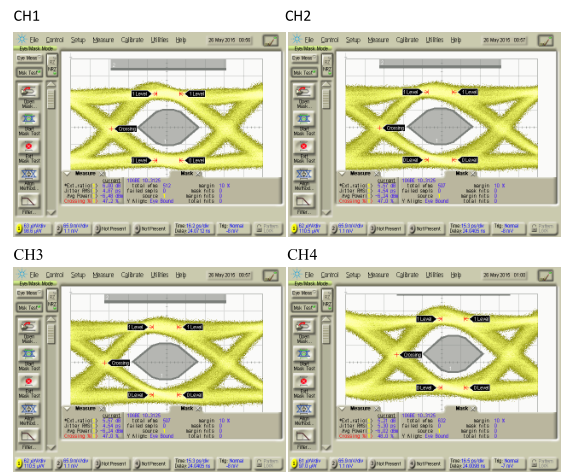
4-Channel Transmitter Eye Diagram at 25 ℃
In IEEE 802.3ba 40G base-lr4, the minimum requirement for transmission power is – 7dBm (per channel) and the maximum requirement is 2.3dbm (per channel). The requirement for extinction ratio is that the minimum value is 3.5db. The experimental results are compared and meet the requirements of the protocol.
Receiver Performance Test
The most important performance index at the receiver is the sensitivity of the receiver. In order to measure the sensitivity of four channels of QSFP+ LR4 module, the transmitting end and receiving end of four bit error meters are connected to the test board of the module, and the transmitting end of the module is connected with an optical attenuator. The attenuated transmitted optical signal is divided into four channels through the wave splitter / combiner, and the limit sensitivity is measured independently for each channel. Each channel is divided into two channels through the beam splitter. One channel is sent back to the receiving end of the module, and the other channel is connected to the optical power meter to measure the actual receiving sensitivity. The test results are shown in the table below.
| Temperature | Channel | Receiver Sensitivity(dB) |
| -10°C | CH1 | -13.5 |
| CH2 | -15.5 | |
| CH3 | -15 | |
| CH4 | -12.6 | |
| 25°C | CH1 | -14 |
| CH2 | -15.2 | |
| CH3 | -15.5 | |
| CH4 | -13.5 | |
| 55°C | CH1 | -12.5 |
| CH2 | -14.6 | |
| CH3 | -15 | |
| CH4 | -12.7 |
The maximum sensitivity requirement in IEEE 802.3ba-2010 40G base-lr4 is – 11.5db. Compare the test results and meet the requirements of the protocol.
Conclusion
This paper introduces the test environment of the 40G QSFP+ LR4 module and the performance test requirements of the transmitter and receiver of the module in detail. The module used in the test is 40g qsfp + LR4 of QSFPTEK company. The experimental results show that the performance of the module fully meets the protocol specification. Besides the 40G QSFP+ LR4 transceiver, QSFPTEK also provides high-quality and high-reliable 40G QSFP+ SR4, 40G QSFP+ ER4, and etc with industry-leading hardware optical components. Welcome to consult via sales@qsfptek.com.